Clock Tree Synthesis is a process of automatic insertion of buffers/inverters along the clock path to balance the clock delay to all the clock inputs in the asic design.
Since some amount of delay is associated with every physical wire due to RC factor associated with it, it will results into clock not reaching to the clock pin of all the flops at same time in the design. So by adding buffers/inverters ,we try to maintain Zero skew (ideally impossible) and minimum insertion delay by means of CTS.
Selecting a set of particular buffers and inverters plays a very important role ,which decides the performance of design.
If clock buffers are not selected correctly they may cause the clock pulse width to degrade as the clock propagates through them.
In most of the ICs clock consumes 30-40% of total power. So efficient clock architecture, clock gating & clock tree implementation helps to reduce power.
CTS Goals:
a) Meeting the clock tree DRC's which includes
▪ Max. Transition:
should not be too tight and too relaxed
The Transition of the clock should not be too tight or too relaxed.
If it is too tight then we need more number of buffers.
If it is too relaxed then dynamic power is more.
▪ Max. Capacitance
▪ Max. Fan-out
b) Meeting the clock tree targets.
▪ Minimal skew: For this this reason we will need to synthesize the clock tree
▪ Minimum insertion delay
c) After CTS we should meet all the Hold Violations.
CTS steps:
▪ Create clock spec file,
▪ Create clock tree, compile clock tree by (Create_clock)
▪ Fine tune clock tree,for meeting clock skew and insertion delay (ClockOpt)
Implementing Clock Tree:
For implementing the clock tree, use the clock-opt which performs
* CTS &
* incremental physical optimization.
Synthesizes the clock Tree:
Before implementing the clock tree, the tool upsize & possible moves the existing clock gate which improves the quality of result (QoR) and reduce the number of clock tree levels.
Optimize the Clock Tree: is done by any of following steps
▪ Buffer relocation.
▪ Buffer sizing.
▪ Gate relocation.
▪ Gate sizing.
▪ Improve skew.
▪ Delay insertion.
▪ Perform inter-clock delay balancing
▪ Balancing has to be done between two flops driven by two different clocks.
▪ Clock groups between which balancing have to be performed need to be specified.
▪ Perform detail routing of clock nets [NDR rule].
▪ Apply non default routing (NDR) rules for clock nets.
Double width & Double spacing.
Shielding
▪ By default the tool applies routing rules for sink pin. It is better to use normal routing rules at the sink pin because to reduce the congestion and tapping of clock might be easy.
▪ Perform RC extraction of the clock nets and compute accurate clock arrival time.
▪ Adjust the I/O timings.
After implementing the clock tree, the tool can update the input and output delays to reflect the actual clock arrival time.
▪ Perform power optimization.
Use a large/Max clock gating fanout during insertion of the ICG cells.
Merge ICG cells that have the same enable signal.
Perform power-aware placement of ICG and registers.
▪ Check and fix any congestion hotspots.
▪ Optimize the scan chain.
▪ Fix the placement of the clock tree buffers and inverters.
▪ Perform placement and timing optimization.
▪ Check for major hold time violation.
Clock Tree Exceptions:
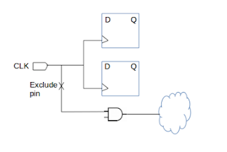
Clock tree exceptions are declared before clock tree synthesis to guide the tool for timing analysis and skew balancing. We can control clock tree tracing by including or excluding particular pins explicitly.
To define clock tree exceptions, use the set_clock_tree_exceptions command or choose Clock > set Clock Tree Exceptions in the GUI. We can set clock tree exceptions on pins or hierachical pins.
ICC prioritizes the clock tree pin exceptions as follows:
1. Nonstop pins
2.Exclude pins
3. Float pins
4. Stop pins
1. Non- Stop Pin:
Nonstop pins are pins that would normally be considered endpoints of the clock tree, but instead ICC traces through them to find the clock tree endpoints. The clock pins of sequential cells driving generated clocks are implicit nonstop pins. In addition, ICC supports user-defined ( or explicit ) nonstop pins.
Example :
The clock pin of sequential cells driving generated clock are implicit non-stop pins.
Clock pin of ICG cells.
2.Exclude Pin: CTS would exclude the pins from Skew analysis.
3.Float Pin: (macro model)
Float pins are clock pins that have special insertion delay requirements and balancing is done according to the delay.
[Macro modelling]. float
4. Stop Pin:
Stop pins are the endpoints of clock tree that are used for delay balancing.CTS, the tool uses stop pins in calculation & optimization for both DRC and clock tree timing.
Example:
Clock sink are implicit stop pins.
5. Leaf Pin:
CTS treats the pins as sinks, stops tracing further and balances clock skew.


